
Installing the VPFlowScope M insertion flow meter
VPInstruments’ VPFlowScope M is a 4-in-1 insertion flow meter: it measures flow, pressure, temperature and totalised flow of a compressed-air or inert-gas line simultaneously. As with any insertion instrument, measurement quality depends first on the installation: installation point, straight pipe lengths, insertion depth and (the setting you must never skip) the inner pipe diameter programmed into the device.
This guide covers, step by step, the under-pressure installation of both cartridges (P350 and P220), the wiring and the configuration. VPInstruments’ official user manual prevails: its figures, illustrations and certificates take precedence over this summary, especially for the safety system and the tightening torques.
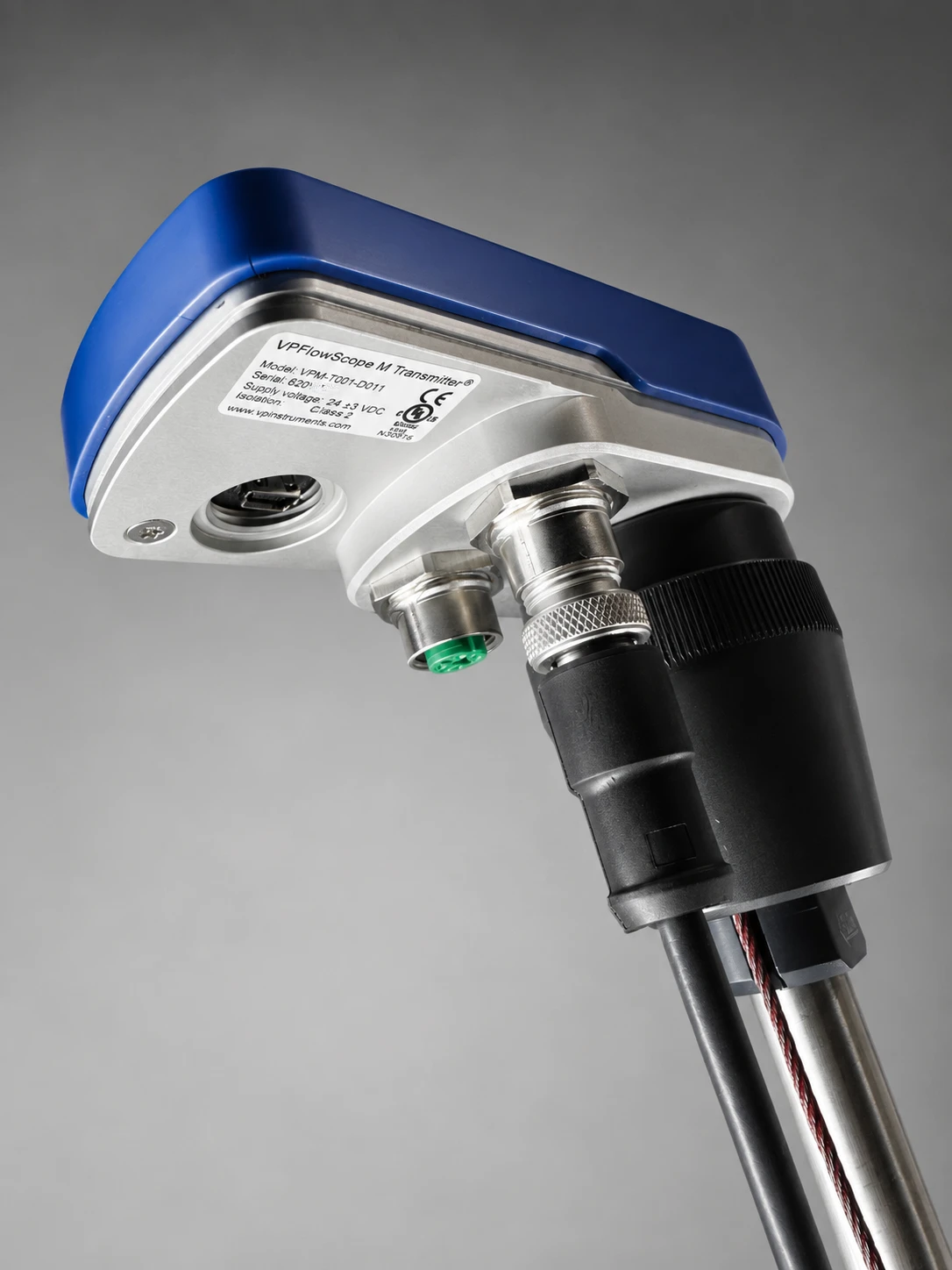
⚠ Safety first. Compressed air is dangerous. Installation is on pressurised equipment: respect local rules for working on pressurised equipment. Always fit the safety system first, keep one hand on the transmitter when opening the valve, and have a qualified person perform the installation. These steps do not replace reading the manufacturer’s manual.
What you install: transmitter + cartridge
The VPFlowScope M consists of two parts:
- The transmitter: “the brains”. It carries the interfaces (RS-485, Ethernet, USB, analog output), the optional display and the optional data logger. Once mated to the cartridge, it rotates 360° to orient the display (loosen the locking ring, hand-tighten it once in place).
- The VPSensorCartridge: it holds the sensors and its calibration characteristics. That is what makes calibration exchangeable: you swap the cartridge instead of recalibrating (see below). It carries a flow direction arrow that also serves for alignment.
Two cartridge families exist. The choice depends on the working pressure and the diameter of the pipe.
| Cartridge | Pressure | Diameters | Probe length | Safety system |
|---|---|---|---|---|
| P350 (P35X, PN10) | 0–10 barg | 0–145 psig | 25 to 1016 mm (1″–40″) | 340 mm | 13.4 in | Separate safety cable + plate + auto-brake |
| P220 (P22X, PN16) | 0–16 barg | 0–250 psig | 22 to 115 mm (0.87″–4.5″), recommended below 80 mm | 220 mm | 8.67 in | Lock integrated in the compression fitting |
Note: Between 1″ and 2″, the field accuracy of a P350 cartridge drops to ~10 % (installation errors weigh more on small diameters). Below 80 mm, prefer a P220.
The safety system
The safety system is designed specifically for the VPFlowScope M: it prevents the probe from being ejected from the compression fitting by the pressure. Understand it before installing.
- P350 cartridge: 1/2 inch compression fitting with a Teflon ferrule, a safety plate (links fitting and system), an auto-brake (the cable slides up only when the lock is pushed down) and a safety cable attached to the cartridge. The cable length is sized so the probe can never leave the fitting.
- P220 cartridge: the cartridge sits in a compression fitting with an integrated safety lock, leak-proof, where the probe is held by an additional ring. This setup also makes the insertion depth easy to adjust. (Test certificate available on request from the manufacturer.)
⚠ Never mix the safety mechanisms of one family with another, and never modify them. The P350 Teflon system and the P220 integrated lock are not interchangeable.
1. Choose the installation point
The installation point is crucial to a correct reading. Error sources are many: imprecise installation, uneven flow profile, swirls, rapid pressure or temperature swings, humidity variation, sensor contamination.
Look for a location that:
- is accessible for wiring and maintenance;
- stays within specifications (exceeding pressure or temperature distorts the reading and can damage the sensor);
- imposes no mechanical stress on the instrument (it is a precision device).
Avoid: excessive heat, high humidity and dripping (the device is not watertight, use a protective cover outdoors), corrosive atmospheres, voltage spikes and EMF, vibration (power tools, foot bridges, fork-lift trucks).
⚠ Allowed gases and maximum pressure. Only air, nitrogen and other non-hazardous, non-combustible gases. Respect the maximum working pressure: P350 → 0–10 barg (145 psig), P220 → 0–16 barg (250 psig).
2. Respect the straight pipe lengths (piping table)
Gas in a pipe follows physical laws: it needs sufficient straight lengths upstream and downstream of the device. The values below (×D, where D = inner diameter) are minimums; you can always make the upstream longer. They are industry-wide guidelines, never a guarantee of the “true value”.
| Disturbance | Upstream (min.) | Downstream (min.) | Effect |
|---|---|---|---|
| Single elbow | 30 × D | 10 × D | Distorted flow profile |
| Complex feed-in (header) | 40 × D | 10 × D | Distorted profile |
| Double / consecutive elbows | 40 × D | 10 × D | Distorted profile + swirl |
| Expansion (small → large) | 40 × D | 5 × D | Jet-shaped flow |
| Reduction (large → small, 7–15°) | 10 × D | 5 × D | Flattened profile |
Note: If the upstream is straight and the disturbance is downstream, use the “downstream” column. In very complex situations (multiple disturbances), change location rather than compromise.
3. Prepare the tap
- Create a tap with 1/2 inch female thread. For an under-pressure installation, use a hot-tap saddle.
- Install a DN15 full-bore ball valve (female BSP or NPT): it lets you insert and retract the cartridge.
- Drilling: the hole must be at least 17 mm (0.67 in) and completely clear. Never force the cartridge in, you would damage it (wrong reading or none).
4. Insertion depth and orientation
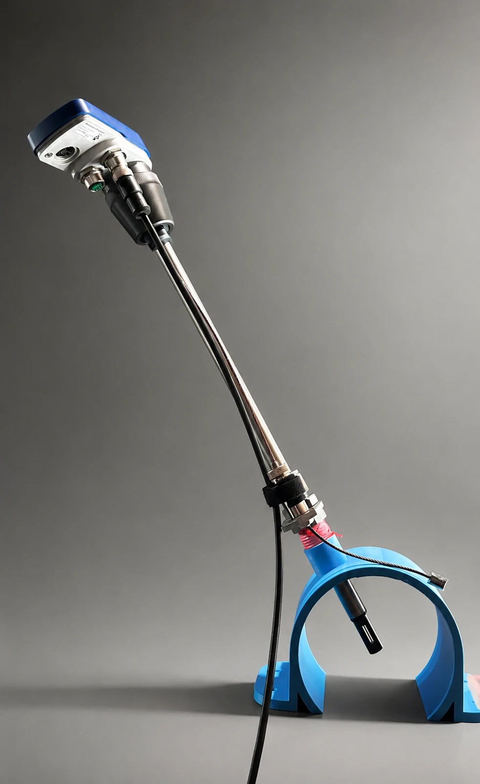
Depth. General rule: 0.5 × the inner diameter, sensor tip at the centre of the pipe (diameters > 65 mm | 2.5 in). The stem is graduated to read the depth.
- Between DN25 and DN65: push the probe almost to the bottom of the pipe, otherwise the temperature sensor leaves the flow path. The reading is corrected automatically for these small diameters.
- Above 65 mm | 2.5 in: the tip must be at the centre.
Orientation. Install the device upwards, between 1 and 2 o’clock (never upside down). Align the flow direction arrow with the actual flow: one marker is on the cartridge, a second on the safety system. Alignment “by the eye” is enough; a ruler placed on the flat of the marker helps if needed.
5. Assemble and install the P350 cartridge
Safety first: start by fitting the safety cable. The probe is sealed by a Teflon ferrule (which can become slippery); the cable holds the probe if it leaves the fitting. Never over-tighten the compression fitting, you would damage the probe. Torque per the manual: 1 N·m in normal use, 2.5 N·m maximum in extreme cases, only when necessary.
Prepare the fitting. Remove the compression fitting’s parts on the long threaded end, place the safety plate over that end, fit and tighten the nut, then refit the Teflon rings and nut.
Assemble the instrument:
- Lift the safety cable, slide the locking ring over the cable, then pass the cartridge through the ring into the compression fitting.
- Attach the safety cable to the cartridge (it should snap in fully), then move the locking ring up over the cartridge and hold it.
- Place the transmitter on the assembly, align the probe with the display (default position, arrow to the left per the manual’s illustration) and tighten the locking ring completely.
- Check that the safety cable is secured.
- Ball valve closed (the probe stays in the fitting), check that the safety system is locked, then mount the assembly on the ball valve.
- One hand on the transmitter: when installing into a pressurised system, temporary leakage around the fitting and an upward push are normal as long as the safety system is correctly fitted. Open the valve slowly and lower the probe gently until the tip is in the centre. Hand-tighten the fitting, then a further 1/2 turn with a wrench.
- Unscrew the safety lock, pull the cable tight, retighten the lock, then align the flow direction (by the eye).
6. Assemble and install the P220 cartridge
Safety first: start by fitting the safety cable. The compression fitting with integrated lock holds the probe. Never over-tighten. Torque per the manual: 15 to 25 N·m, without exceeding 25 N·m.
- Ball valve closed (the probe stays in the integrated-lock fitting), mount the integrated-lock compression fitting on the ball valve.
- Place the transmitter on the cartridge, align the probe with the display (arrow to the left per the manual) and tighten the locking ring completely.
- One hand on the transmitter, open the valve slowly and lower the probe gently. For the P220, the tip sits 5 mm from the end of the pipe. Align the flow direction (by the eye).
- Hand-tighten the clamp nut, then tighten with a wrench.
7. Wire the electrical connections
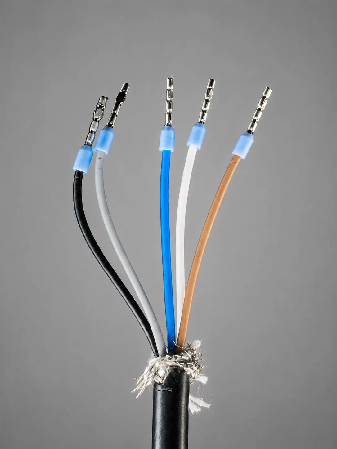
⚠ Never use AC power: it voids the warranty and destroys the electronics. Connect the M12 connector before applying power.
The transmitter takes an M12 5-pin connector (power + analog output + Modbus RS-485):
| Pin | Signal | Wire colour* |
|---|---|---|
| 1 | +14…24 VDC | Brown |
| 2 | 0 V | White |
| 3 | 4–20 mA, active | Blue |
| 4 | RS-485 B/+ | Black |
| 5 | RS-485 A/− | Grey |
Colours apply to VPInstruments cables.
- Power: 14 to 24 VDC, Class 2 source (< 2 A). Ensure at least 14 V at the connector, long cables cause voltage drops (the display warns of insufficient power). For maximum reliability, 24 VDC is recommended.
- Cabling: shielded twisted pair, shield connected to safety ground at a single point. Below 300 m, 20 AWG; beyond, 18 AWG or better.
- Ground loops: do not combine the 24 V supply, a mains-powered laptop and the USB cable at the same time. Use the laptop on battery, or a USB isolator.
- Analog output: configurable as 4–20 mA, pulse or alarm (one at a time).
- Ethernet: available on an M12 4-pin connector (Modbus TCP; DHCP by default). RS-485: daisy-chain network (never star or ring), 120 Ω termination resistor at the last node beyond 10 m.
8. Configure: program the inner diameter
This is the only mandatory setting. The sensor measures a velocity; the instrument converts it into flow from the inner pipe diameter. A wrong diameter = a very wrong reading.
- Fastest: program the inner diameter on the display keypad.
- Otherwise: over Modbus (RS-485, USB) or Modbus TCP (Ethernet), or with the VPStudio software (Windows, free from VPInstruments), a graphical interface equivalent to a Modbus master.
- Programmable ranges: P350 → 25 to 1016 mm (0.98″–40″) ; P220 → 22 to 115 mm (0.87″–4.5″).
Advanced settings as needed (display, Modbus or VPStudio): Ethernet/IP address, 4–20 mA / pulse / alarm boundaries, device date and time.
9. Commission and read
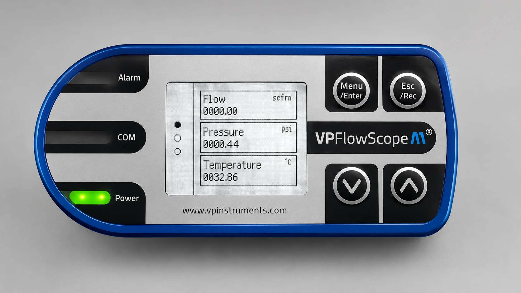
At power-up, the display shows measurement pages (1, 2 or 3 measurands, configurable; navigate with ▲▼ and Menu/Enter). Three LEDs report status:
- green blinking (2 s): waiting for a cartridge; green steady: cartridge detected, ready;
- orange fast blink: RS-485 or USB communication;
- red steady: active alarm; red blinking (1 s): cartridge error (see display / VPStudio).
The optional data logger holds one year of data (circular memory, 1 sample/s). Set the date and time (UTC): without it, or after more than 5 days without power, data may be overwritten.
10. Replace the cartridge (instead of recalibrating)
The calibration lives in the cartridge: recalibration reduces to an exchange, settings kept and near-zero downtime.
- P350 cartridge: no need to remove everything, the safety system stays in place. Unscrew the safety lock and lift the cable to the end stop; with one hand on the transmitter, slowly loosen the fitting, lift the probe until the cable is taut, close the valve. Unscrew the locking ring, remove the cable from the old cartridge, replace the cartridge, then resume the assembly (cable, ring, transmitter, slow opening under pressure, centring, hand-tighten + 1/2 turn, tension the cable).
- P220 cartridge: remove the complete assembly (the safety system is attached to the cartridge): loosen the clamp nut, with one hand on the transmitter lift the probe, close the valve, unscrew the integrated-lock fitting and take out the cartridge, then refit the new one as in section 6.
Reference specifications
Always check the nameplate of your device. Specifications change; request the latest data sheet from VPInstruments.
| Parameter | Value |
|---|---|
| Principle (flow) | Insertion thermal mass (Thermabridge™), no bypass flow |
| Reference conditions (flow) | DIN 1343 by default (0 °C, 1013.25 mbar); also ISO 1217 (FAD) and ISO 2533 |
| Accuracy (flow) | 2 % of reading for Ø > 50 mm (2″); small Ø: P220 ~3 %, P350 ~10 % |
| Pressure | P350: 0–10 barg (145 psig) · P220: 0–16 barg (250 psig) |
| Gas temperature | 0–60 °C | 32–140 °F |
| Gases | Compressed air, nitrogen, non-condensing inert gases |
| Protection grade | IP65 | NEMA 4 (transmitter + cartridge mated, USB cap tightened) |
| Power | 14–24 VDC, Class 2 (UL); 1 W idle, 3.5 W at full flow |
| Process connection | Compression fitting, 1/2 in NPT tapered |
| Certification | CE · UL 508 (check the marking on the nameplate) |
Where Onyx M3 comes in
Measuring accurately starts with installing the instrument well. Onyx M3 supports you on the cartridge choice (P350 / P220 by pressure and diameter), the measurement point (straight lengths, depth), the under-pressure installation and the integration into energy monitoring (Modbus, VPVision, dashboard). Our selection support is offered even without a purchase on the site, the goal is for your measurement to be reliable, not just for the device to be wired in.
To integrate this signal into a complete infrastructure, see our turnkey industrial telemetry service.
References
- Official user manual: VPFlowScope M, VPInstruments (source of truth: figures, illustrations, safety).
- Product page: VPFlowScope M: insertion flow meter
- Flow units: normalised, standard, SCFM: understanding the displayed flow.
- Sizing compressed-air piping: why the inner diameter matters.
- Pipe diameter chart ID/OD (steel, stainless, aluminium): TUY-REF-001, for programming the inner Ø and insertion depth.
- Compressed-air calculator: convert units and estimate flow.