
Sizing compressed-air piping: flow, length, velocity and pressure drop
A line that is too small chokes the flow and drops the pressure; every psi lost in the piping is energy paid to the compressor and then wasted. So a line is sized on two simultaneous criteria (air velocity and pressure drop) from four inputs: flow, length, working pressure and allowable drop.
The four inputs
| Input | What to enter | Common pitfall |
|---|---|---|
| Flow | The peak simultaneous flow (SCFM) through the section | Adding up every tool’s nameplate when they never all run at once |
| Length | The developed length of the pipe you will actually install + the equivalent length of fittings | Forgetting the fittings; pre-dividing a loop |
| Working pressure | The real network pressure (psig) | — |
| Allowable drop | The pressure drop you accept on this section (psi) | Aiming too generously |
Flow is given in SCFM (standard cubic feet per minute); see Flow units to convert it correctly and not confuse it with ACFM.
Criterion 1: air velocity
Lines are first sized on velocity: too fast, the air turns turbulent, noisy, and carries water and debris past the drain legs.
| Section | Target velocity | Do not exceed |
|---|---|---|
| Main line / header | ≤ 20 ft/s (6.1 m/s) | 30 ft/s (9.1 m/s) |
| Drop / local feed | ≤ 30 ft/s (9.1 m/s) | 33 ft/s (10 m/s) |
Why these velocities? CAGI (handbook, ch. 4) recommends that velocity in distribution piping not exceed 30 ft/s (9.1 m/s); to keep liquid water from being carried past the drain legs in main distribution lines, it should not exceed 20 ft/s (6.1 m/s). A branch line with a velocity above 33 ft/s (10 m/s) should not exceed 50 ft in length. The British Compressed Air Society (BCAS) holds the same 20 ft/s (6 m/s) benchmark for mains; beyond that you add erosion and noise. Our calculators flag any velocity above an absolute ceiling of 35 ft/s (~10.7 m/s).
Criterion 2: pressure drop (the deciding criterion)
Velocity is a guardrail, but pressure drop is usually what sets the diameter. CAGI sets the reference rule: pressure drop between the compressor discharge (P2) and the point of use should not exceed 10% of the discharge pressure, and a drop to a station should stay under 1 psi. Network manufacturers aim tighter on distribution alone: ≤ 1.5 psi (0.1 bar) from the compressor to the farthest point of use, hoses and fittings included (Prevost sizes its tables at 116 psi / 8 bar with a 5% loss, i.e. ≈ 5.8 psi / 0.4 bar).
This is energy. CAGI notes that at a nominal 100 psig, every 2 psi change in discharge pressure changes a positive-displacement compressor’s power by about 1%. Lowering the set pressure by 10 psi therefore cuts consumption by about 5%. Undersized piping forces you to raise that set pressure to compensate: you pay for the loss twice.
The filters and the dryer also consume pressure drop: budget them in the total. See line filters and dryers.
Fittings count: the equivalent length
Every elbow, tee or valve behaves like an extra length of straight pipe. Together, fittings add an equivalent length often comparable to that of the straight pipe, so they cannot be ignored.
The method: add an equivalent length per fitting (Le/D ratio). Common values (Crane TP-410): 90° elbow ≈ 30 × D, branch-flow tee ≈ 60 × D; CAGI (handbook ch. 4, table 4.15) publishes these equivalent lengths directly in feet per nominal diameter. The design length becomes: developed length + sum of equivalent lengths. The more elbows and tees a layout has, the larger the diameter required, hence the value of a clean geometry. See Saddle-branch takeoff and Drop and outlet manifold.
Open line or loop: where the length is measured
This is the most confusing point. The rule is simple: always enter the pipe you actually install, then state the topology; the calculation applies the physics.
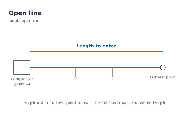
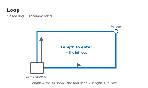
In an open line, a single run goes from the supply point out to the stations: simple, but the full flow crosses the entire length, giving a larger diameter and a bigger drop at the far end (“air starvation” at distant stations). In a loop, the line returns to the supply point: each station is fed from both sides, so the longest path and the per-branch flow are about halved. The result: a smaller diameter for the same drop, steadier pressure, and the ring acts as buffer storage. As Prevost puts it: looping the system can cut your pressure drop in half, with a minimum of elbows.
Key point: for a loop, enter the full length of the ring (back to the supply point), not half: the tool applies the ÷2 itself. If you fed it the half-length, the network would be undersized.
Material: why aluminium
For the same diameter, a smooth-bore aluminium tube offers less friction than steel. Above all, it does not corrode: the bore stays clean and the diameter is maintained for years, whereas black or galvanised steel scales up (rust shrinks the bore, adds drop and creates leaks, sometimes within months). Its fittings are full-flow, with no restriction, and the network is easy to modify. See the EQOfluids network accessories, the exact tube dimensions (PN16 / PN70) and Pipe supports and fixing.
Installation best practices
- Oversize slightly for leaks and future expansion: one size up costs little, the pressure-drop saving is permanent.
- Main line ≥ 2.5 m off the floor, drops terminating around 1.2 m (Prevost).
- Take air off the top of the main (takeoff over the top) so condensate is not dragged into the drop; a slight slope toward drain points. See Water in the compressed-air system.
With the Onyx M3 tools
- Network estimator: enter the flow, the actually-installed length and the topology: it sizes the main line AND each drop (on its own tool flow), then builds the bill of materials ready to add to your quote.
- Calculator: pipe sizing: compares under / optimal / over diameters by pressure drop and by velocity, open and closed loop. Take the larger of the two (the safer choice).
- Pipe diameter chart ID/OD (TUY-REF-001): inside and outside diameters for steel, stainless and aluminium when selecting and programming the real Ø.
In both cases: enter the pipe you actually install, pick the topology, and let the tool apply the physics (½ length + ½ flow for a loop).
References
- CAGI: Compressed Air & Gas Handbook (7th ed., 2021), Chapter 4 “Compressed Air System Design”: distribution velocity ≤ 30 ft/s, main lines ≤ 20 ft/s (water carryover), branch lines > 33 ft/s limited to 50 ft; pressure drop ≤ 10% of discharge pressure; equivalent lengths of fittings (Table 4.15); 2 psi = 1% power rule
- Crane: Technical Paper No. 410 (TP-410), Flow of Fluids Through Valves, Fittings and Pipe: equivalent lengths (Le/D) of fittings
- British Compressed Air Society (BCAS): recommended velocities (20 ft/s main, 30 ft/s drop)
- Atlas Copco: compressed-air piping sizing (velocity 20–30 ft/s, pressure drop ≤ 1.5 psi / 0.1 bar)
- Prevost: Prevost Piping System, technical documentation (loop = ½ the drop, install heights)
- EQOfluids: DN20–DN160 aluminium network